25+ instrumentation amplifier block diagram
To compensate for the reduction in loop gain due to it the proposed CFIA uses folded cascode OTA FC-OTA in the. The objective of this experiment is to study some of the special amplification systems used in biomedical signal processing.
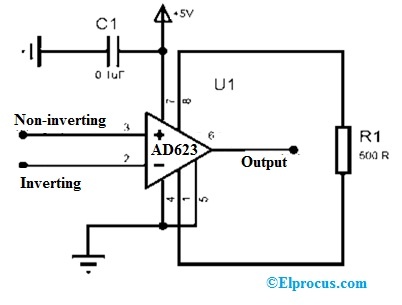
Ad623 Instrumentation Amplifier Datasheet Working Its Applications
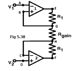
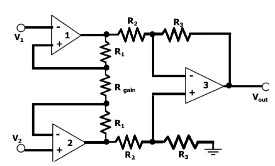
The op-amp A 3 is the normal difference amplifier forming an.

. The op-amps A 1 and A 2 are the noninverting amplifiers forming the input or first stage of the instrumentation amplifier. Shows the basic operation of classic three op-amp based instrumentation amplifier Basic block diagram of instrumentation amplifier is shown in Fig 1. The integrated input-referred noise is 175 from 05 Hz to 100 Hz.
Enabling the CMFF improves the CMRR by 25 dB. These amplifiers serve the needs of high precision analog voltage. Which is typically G 1 VV for most instrumentation amplifiers the overall gain is driven by the amplifier in the first stage.
Block diagram of CFIA 11 input stage to reduce the noise and area. The CALEX instrumentation amplifier block is built around the classical current feedback differential amplifier. Instrumentation Amplifier Document Number.
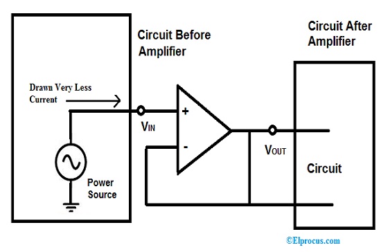
Block diagram of amplifier The figure below shows the block diagram of an amplifier. Block diagram of sensor interface to INA. Instrumentation Amplifier PRODUCT DESCRIPTION The AD624 is a high precision low noise instrumentation.
The circuitry involved inside. There are two main inputs V CM and V. The selection of analog ground and gain value determine the usable input.
G Page 3 of 22 fixed-scale ADCs for 50V operation. The TDA2040 is amplifying the signal and providing 25Watt RMS wattage to the 4 ohms loudspeaker. Here as we can see the transmitted signal is fed to the amplifier as input.
This instrumentation system consists of a type of transducer as the input stage depending upon. 025 µVC output offset voltage drift of less than 10µVC. The schematic for 25 watt audio amplifier is pretty simple.
The ECG-Amplifier Project Lab. 15 shows the CMRR of one EEG channel including two AEs and one BE. The simplified form of such an instrumentation system is shown in Fig.
An instrumentation amplifier is a closed-loop gain block that has a differential input and an output that is single-ended with respect to a reference terminal.

Lm741 Op07 Lm324 Ad620 Instrumentation Amplifier
Instrumentation Amplifier Circuit Diagram Advantages And Applications
Isolation Amplifier Design Methods Circuit And Its Applications

Ad620 Instrumentation Amplifier Pinout Circuit Parameters Faq

Simple Instrumentation Amplifier Circuit Diagram Using Opamp Equation For Gain Design Working And Construction Also Provide Circuit Diagram Amplifier Diagram

Practical Instrumentation Amplifier Circuit Circuit Diagram Amplifier Electronic Engineering

Ad620 And Pic10f206 Based Pointer Galvanometer Design
Instrumentation Amplifier Circuit Design And Applications Circuit Design Amplifier Circuit

Instrumentation Amplifier Circuit Using Op Amp Circuit Diagram Electronic Circuit Design Circuit
Instrumentation Amplifier Circuit Diagram Advantages And Applications
25 Op Amp Circuits And Projects List

Lm741 Op07 Lm324 Ad620 Instrumentation Amplifier

Lm741 Op07 Lm324 Ad620 Instrumentation Amplifier
Instrumentation Amplifier Circuit Diagram Advantages And Applications

Instrumentation Amplifier Circuit Using Op Amp Amplifier Electronics Circuit Electronics Basics

Lm741 Op07 Lm324 Ad620 Instrumentation Amplifier

Ad620 Instrument Amplifier Principle Application